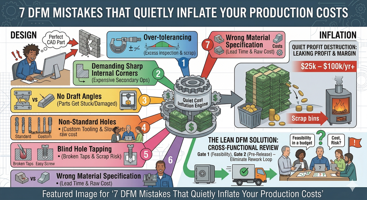
7 DFM Mistakes That Quietly Inflate Your Production Costs
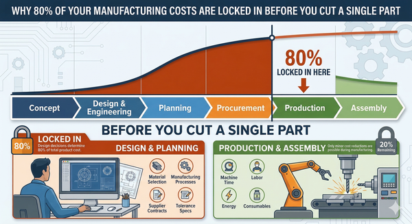
Design for Manufacture (DFM) isn’t optional—it locks in 70–80% of your cost. Poor early decisions drive complexity, waste, and margin loss. This post breaks down 7 common DFM mistakes in SMEs—and how to fix them before they hit your bottom line.

The Problem: Design Decisions That Cost You Money Long After the Drawing Is Released
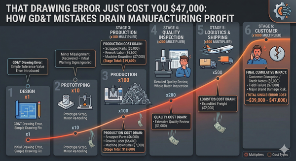
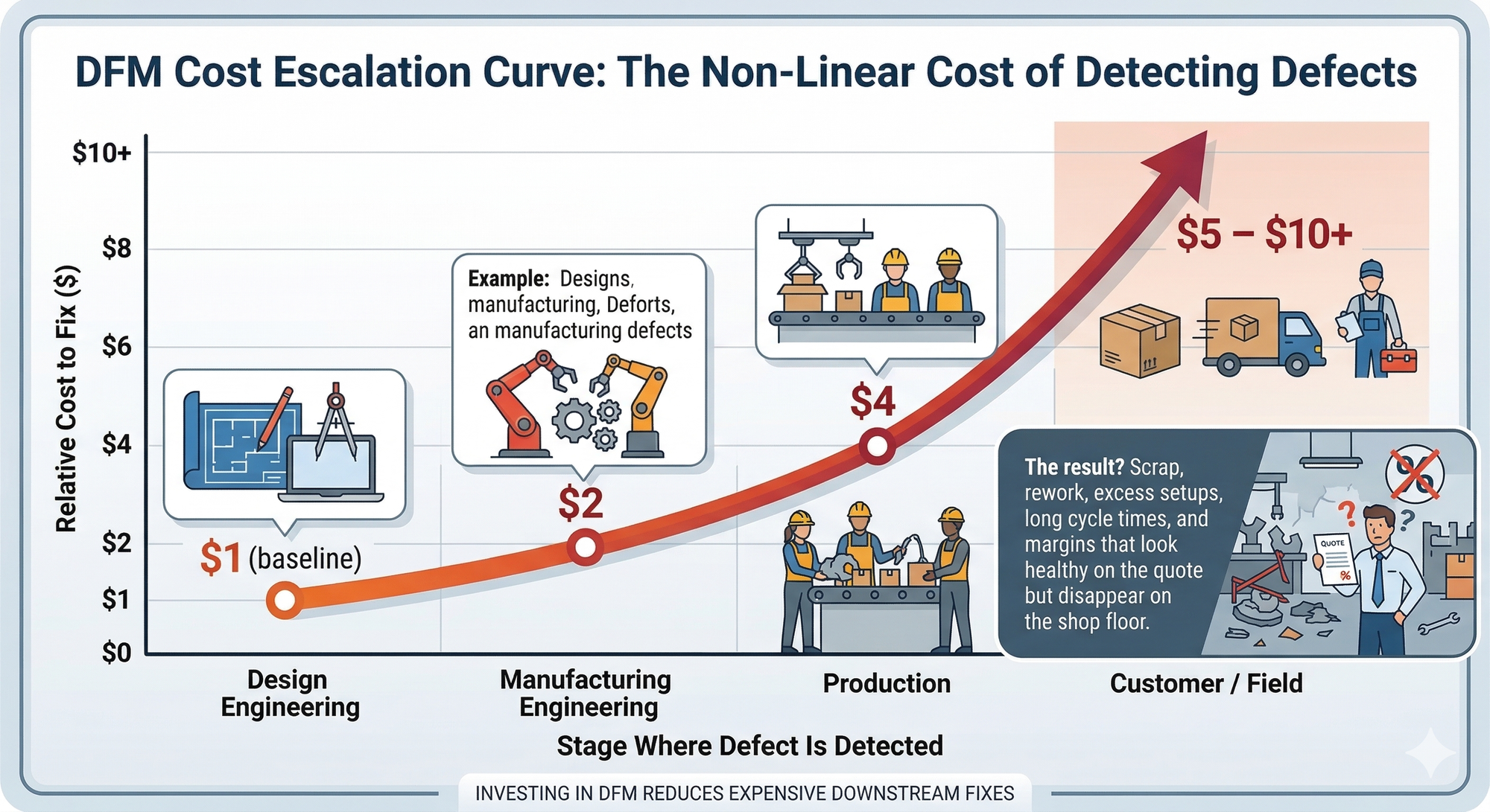
Here's a truth most manufacturers learn the hard way: the cheapest time to fix a problem is during design, and the most expensive time is during production.
The relative cost of correcting a design defect escalates dramatically the further downstream it travels:
| Stage Where Defect Is Detected | Relative Cost to Fix |
|---|---|
| Design Engineering | $1 (baseline) |
| Manufacturing Engineering | $2 |
| Production | $4 |
| Customer / Field | $5 – $10+ |
That's not theory. That's the cost escalation curve from Lean Six Sigma methodology, and it matches what I've seen across two decades of hands-on engineering — from toolmaking through to production line commissioning.
In my experience working with Australian SME manufacturers, the design stage is where the biggest cost levers exist, yet it's the stage that gets the least scrutiny. Engineers focus on function. Sales focuses on features. And production is left to figure out how to actually make the thing — usually under time pressure, with drawings that don't reflect manufacturing reality.
The result? Scrap, rework, excess setups, long cycle times, and margins that look healthy on the quote but disappear on the shop floor.
The 7 DFM Mistakes Bleeding Money from Your Operation
Mistake #1: Over-Tolerancing — Specifying Tighter Than You Need
This is the most common and most expensive DFM mistake I see. Engineers apply tight tolerances across the board "just to be safe," without considering what the part actually requires functionally.
Here's the impact:
| Tolerance Band | Typical Process Required | Relative Machining Cost |
|---|---|---|
| ±0.5 mm | Standard CNC milling | 1x (baseline) |
| ±0.1 mm | Precision CNC, slower feeds | 2–3x |
| ±0.025 mm | Grinding, EDM, or lapping | 5–10x |
| ±0.01 mm | Specialist finishing, CMM inspection | 10–20x |
Every unnecessary tight tolerance adds cycle time, forces slower feed rates, demands better tooling, and increases your inspection burden. Multiply that across hundreds or thousands of parts per year and you're haemorrhaging cash.
The Fix: Apply the principle of functional tolerancing. Ask: "What does this dimension actually control?" If it's a cosmetic surface or a clearance fit, it doesn't need the same precision as a bearing bore or a sealing face. Use GD&T (Geometric Dimensioning and Tolerancing) to communicate design intent clearly, and match your tolerances to your process capability — not to a number you picked from a textbook.
From my toolmaking background, I can tell you that the shop floor respects a drawing that's been thought through. When every dimension is ±0.05 for no apparent reason, the machinist either ignores it (risky) or spends twice the time hitting it (expensive). Neither outcome is good.
Mistake #2: Ignoring Process Capability — Designing Without Knowing What Your Machines Can Actually Hold
This mistake is the cousin of over-tolerancing, but it's more insidious. It happens when the designer doesn't know — or doesn't ask — what the production equipment can reliably achieve.
Every manufacturing process has a natural capability range. If your design demands a tolerance that sits outside that range, you're guaranteeing one of three outcomes: high scrap rates, constant rework, or an investment in equipment you shouldn't need.
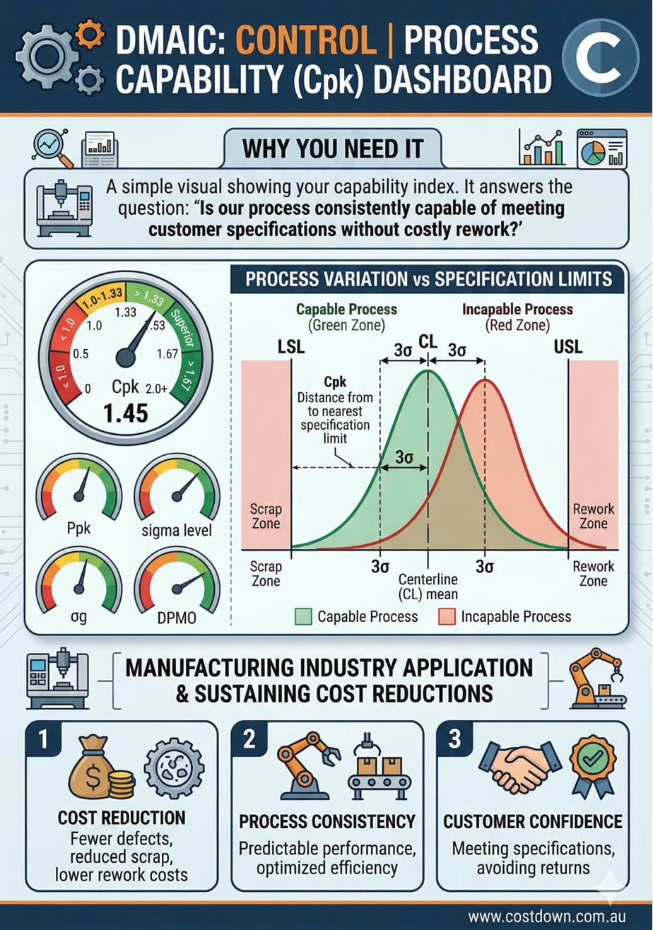
The Fix: Before finalising any design, check your Cpk (Process Capability Index). If your Cpk is below 1.33 for a critical dimension, you have a process that cannot reliably hold the tolerance. You either need to open the tolerance (cheapest), improve the process (moderate cost), or invest in new equipment (most expensive).
| Cpk Value | What It Means | Action Required |
|---|---|---|
| < 1.0 | Process cannot hold tolerance | Redesign tolerance or process |
| 1.0–1.33 | Marginal — high inspection burden | Improve process control |
| 1.33–1.67 | Capable — acceptable for production | Monitor with SPC |
| > 1.67 | Highly capable — minimal risk | Standard production controls |
I've seen manufacturers spend $80,000 on a new grinder to hit a tolerance that could have been opened by 0.05 mm with zero impact on function. That's not engineering — that's waste.
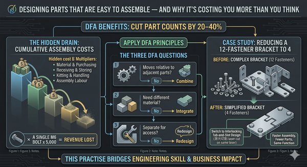
Mistake #3: Excessive Part Count — More Parts, More Cost, More Problems
Every additional part in an assembly adds cost in seven ways: material, machining, handling, storage, inspection, assembly time, and failure risk. Yet many designs carry parts that exist purely because "that's how it was always done" or because the designer didn't consider how the product would actually be assembled.
A Real-World Example: When I designed and commissioned the Ventus Louvre production line, one of the first things we attacked was part count. By simplifying assemblies and designing parts that combined multiple functions, we reduced handling steps, cut assembly errors, and built the entire line for under $50,000. Lower part count was a key enabler of that result.
The Fix: Conduct a DFMA (Design for Manufacture and Assembly) review. For every part, ask three questions:
- Does this part move relative to another part? (If not, can they be combined?)
- Does this part need to be a different material? (If not, can they be combined?)
- Does this part need to be separate for assembly or service access? (If not, combine it.)
The Boothroyd-Dewhurst method suggests that a surprising number of parts in most assemblies exist for no functional reason. Removing even 20% of your part count can slash assembly time by 30% or more.
Mistake #4: Specifying Materials Without Considering Machinability or Supply
Choosing a material based solely on mechanical properties — without considering how it machines, whether it's readily available in Australia, or what it costs in the form factor you need — is a guaranteed margin killer.
I've seen designers specify exotic stainless steels for components that could have been made from standard mild steel with a coating, or call out aluminium grades that have a 12-week lead time from overseas when a locally stocked alternative would do the job.
The Fix: Run a simple decision matrix before locking in any material:
| Factor | Weight | Option A (Specified) | Option B (Alternative) |
|---|---|---|---|
| Mechanical suitability | 30% | 9 | 8 |
| Machinability | 25% | 5 | 8 |
| Local availability | 20% | 4 | 9 |
| Raw material cost (per kg) | 15% | 3 | 7 |
| Surface treatment options | 10% | 7 | 7 |
| Weighted Total | 5.85 | 7.85 |
In this example, the alternative material scores significantly higher when you factor in the full picture — not just tensile strength. The "best" material on paper is often the worst material for your production cost.
Mistake #5: Poor Drawing Practices — Ambiguous, Incomplete, or Unmanufacturable Drawings
A drawing is a contract between design and production. If it's ambiguous, incomplete, or contains conflicting information, the shop floor will interpret it — and interpretation costs money.
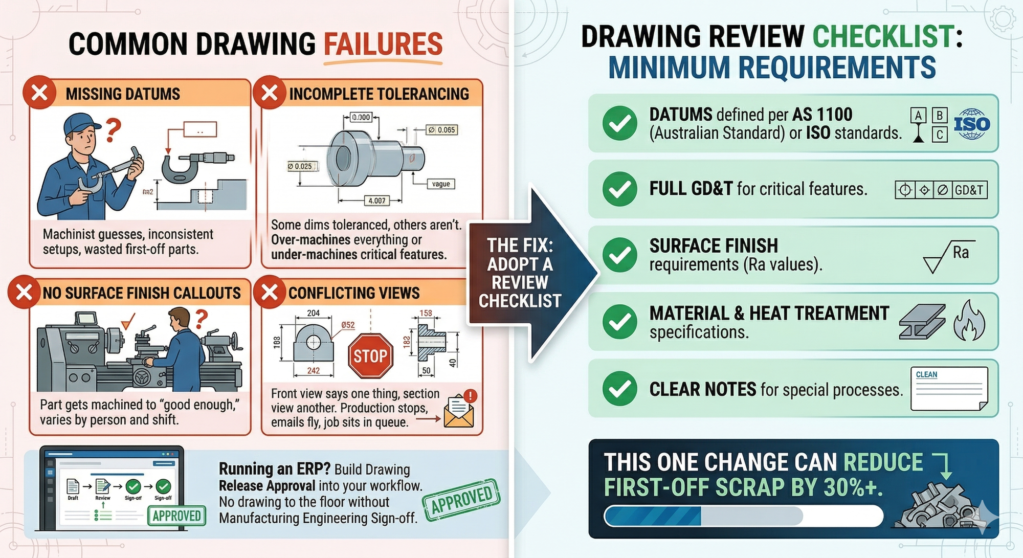
Common drawing failures I encounter:
- Missing datums — the machinist has to guess what to measure from, leading to inconsistent setups and wasted first-off parts.
- Incomplete tolerancing — some dimensions are toleranced, others aren't. Production either over-machines everything or under-machines critical features.
- No surface finish callouts — the part gets machined to whatever the operator considers "good enough," which varies by person and shift.
- Conflicting views — the front view says one thing, the section view says another. Production stops, emails fly, and the job sits in the queue waiting for clarification.
The Fix: Adopt a drawing review checklist before any drawing is released to production. At minimum, every drawing should include: datums defined per AS 1100 (Australian Standard) or ISO standards, full GD&T for critical features, surface finish requirements (Ra values), material and heat treatment specifications, and clear notes for any special processes.
If you're running an ERP system, build drawing release approval into your workflow. No drawing goes to the floor without a manufacturing engineering sign-off. This one change alone can reduce first-off scrap by 30% or more.
Mistake #6: Not Designing for Your Actual Production Method
A part designed for CNC machining looks very different from a part designed for sheet metal fabrication, which looks very different from a part designed for casting. Yet I regularly see designs where the geometry doesn't match the intended process — because the designer either didn't know, or didn't think to ask.
Common examples:
- Internal sharp corners on a milled part — CNC cutters are round. Internal sharp corners require EDM or secondary operations. Cost increase: 3–5x for that feature.
- Bend radii smaller than material thickness on sheet metal — forces cracking, custom tooling, or process workarounds. Cost increase: 2–4x.
- Uniform wall thickness ignored on castings — leads to porosity, sink marks, and high reject rates. Scrap increase: 10–25%.
The Fix: For every part, identify the production method before finalising the geometry. Then design to the natural strengths and limitations of that process:
| Process | Design With the Grain | Design Against the Grain (Costly) |
|---|---|---|
| CNC Machining | Generous internal radii, standard tool sizes | Deep pockets, thin walls, sharp corners |
| Sheet Metal | Bend radii ≥ material thickness, standard tooling | Tight bend radii, complex flanges |
| Injection Moulding | Uniform wall thickness, draft angles | Undercuts, non-uniform sections |
| Welding/Fabrication | Accessible joints, standard profiles | Confined joints, mixed material thickness |
This is where having a toolmaker's eye on your design pays for itself. When you understand what the machine can do naturally versus what it struggles with, you design parts that practically make themselves.
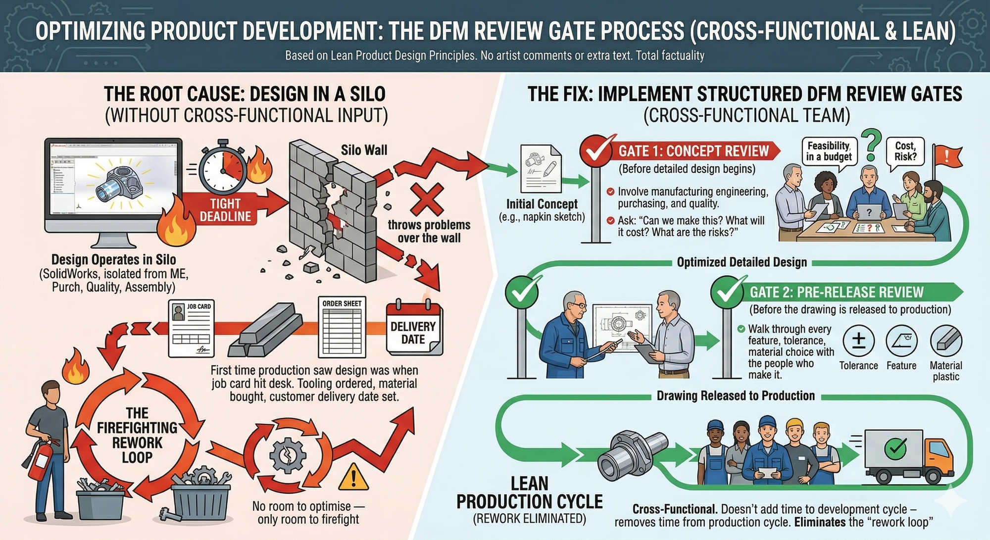
Mistake #7: Designing in Isolation — No Input from Production Until It's Too Late
This is the root cause behind most of the other mistakes on this list. When design operates in a silo — without input from manufacturing, purchasing, quality, or assembly — the result is a product that looks brilliant in SolidWorks and falls apart on the shop floor.
I've worked in environments where the first time production saw a new design was when the job card hit their desk. By that point, the tooling is ordered, the material is bought, and the customer has a delivery date. There's no room to optimise — only room to firefight.
The Fix: Implement a structured DFM review at two critical gates:
- Concept Review — Before detailed design begins. Involve manufacturing engineering, purchasing, and quality. Ask: "Can we make this? What will it cost? What are the risks?"
- Pre-Release Review — Before the drawing is released to production. Walk through every feature, tolerance, and material choice with the people who will actually make it.
This is the cross-functional approach that Lean product design advocates. It doesn't add time to your development cycle — it removes time from your production cycle by eliminating the rework loop that happens when design throws problems over the wall to manufacturing.
Cost / Impact Analysis: What These Mistakes Actually Cost You
To put this in perspective, here's a conservative estimate of the annual cost impact for a typical Australian SME manufacturer running 5,000–10,000 parts per year:
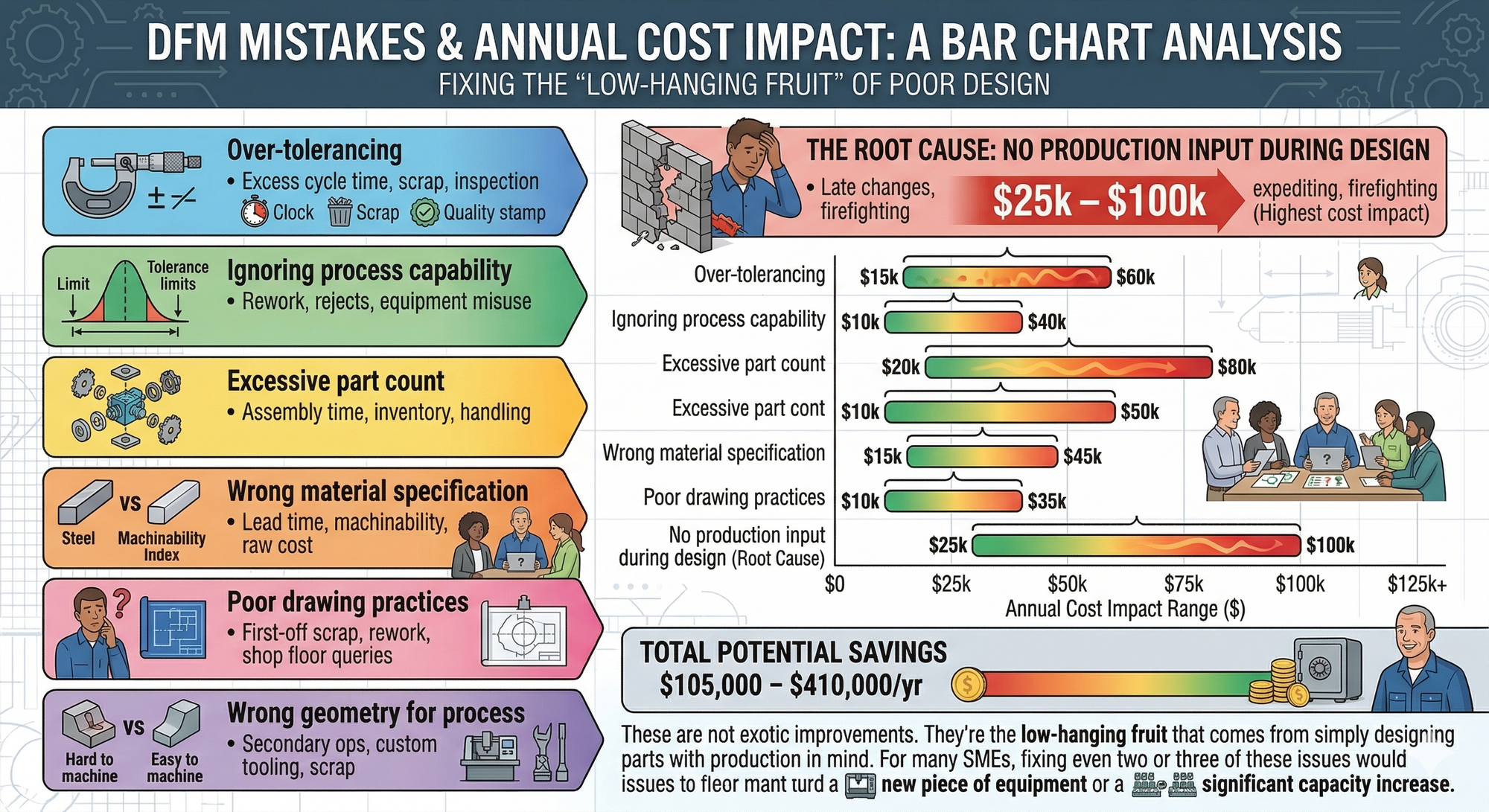
| DFM Mistake | Estimated Annual Cost Impact | How It Shows Up |
|---|---|---|
| Over-tolerancing | $15,000 – $60,000 | Excess cycle time, scrap, inspection |
| Ignoring process capability | $10,000 – $40,000 | Rework, rejects, equipment misuse |
| Excessive part count | $20,000 – $80,000 | Assembly time, inventory, handling |
| Wrong material specification | $10,000 – $50,000 | Lead time, machinability, raw cost |
| Poor drawing practices | $15,000 – $45,000 | First-off scrap, rework, shop floor queries |
| Wrong geometry for process | $10,000 – $35,000 | Secondary ops, custom tooling, scrap |
| No production input during design | $25,000 – $100,000 | Late changes, expediting, firefighting |
| Total Potential Savings | $105,000 – $410,000/yr |
These are not exotic improvements. They're the low-hanging fruit that comes from simply designing parts with production in mind. For many SMEs, fixing even two or three of these issues would fund a new piece of equipment or a significant capacity increase.
The DFM Checklist: A Practical Starting Point
Before releasing any design to production, run through this checklist:
- [ ] Tolerances justified — Every tight tolerance has a functional reason. Non-critical dimensions use standard tolerances.
- [ ] Process capability confirmed — Critical tolerances checked against Cpk data for the production equipment.
- [ ] Part count minimised — Every part reviewed against the "Does it need to be separate?" test.
- [ ] Material validated — Machinability, local availability, and cost in required form factor all checked.
- [ ] Drawing complete and unambiguous — Datums, GD&T, surface finishes, and material callouts all present.
- [ ] Geometry matches production method — Features designed to the strengths of the intended process.
- [ ] Production team consulted — Manufacturing, quality, and purchasing have reviewed and signed off.
Key Takeaway
A product's design determines the vast majority of its manufacturing cost. By the time you've released a drawing, you've locked in roughly 80% of production expense — material, cycle time, tooling, assembly, and quality burden. The seven mistakes in this post are not rare or obscure. They're happening right now, on shop floors across Australia, quietly bleeding margin from businesses that think they have a production cost problem when they actually have a design cost problem.
Fix the design. Fix the cost.
Ready to Find the Hidden Cost in Your Designs?
If you suspect your production costs are higher than they should be — or if you're launching a new product and want to get DFM right the first time — I can help.
I offer a short CostDown Audit that reviews your current designs, drawings, and production processes to identify where money is being lost and where quick wins exist. With 25 years of engineering and production experience, including toolmaking, R&D design, jig and fixture design, and full production line commissioning, I bring the kind of cross-functional perspective that catches the issues others miss.