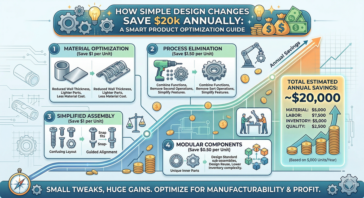
How Simple Design Changes Save $20k Annually
Most SMEs chase savings in labour and materials—but the biggest lever is product design. Tight tolerances, excess parts, and poor material choices quietly drain cash. Here are five simple design changes that can save $20k+ a year.

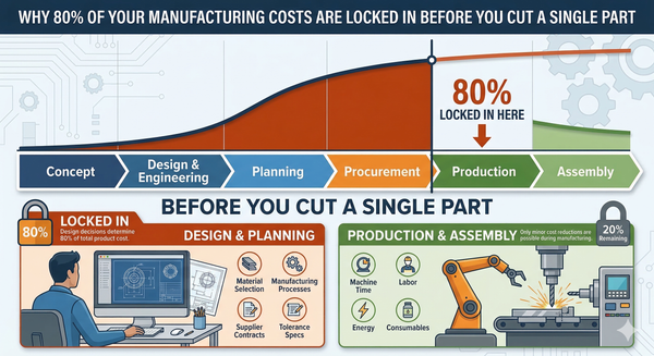
The Problem: Your Design Is Your Biggest Cost Driver
Here's something most manufacturing business owners don't hear often enough: your product design determines 70–80% of your total manufacturing cost. Not your labour rate. Not your material supplier. Your drawings.
Once a design is locked in and released to production, most of the cost is baked in. The tooling is made. The processes are set. The suppliers are chosen. And every inefficiency in that design — every unnecessarily tight tolerance, every extra fastener, every exotic material choice — gets multiplied across every unit you produce, every week, every year.
I've walked factory floors where the operators knew a part was over-engineered, but nobody had ever gone back to the drawing to fix it. The attitude is: "It works, don't touch it." But "it works" and "it works efficiently" are two very different things.
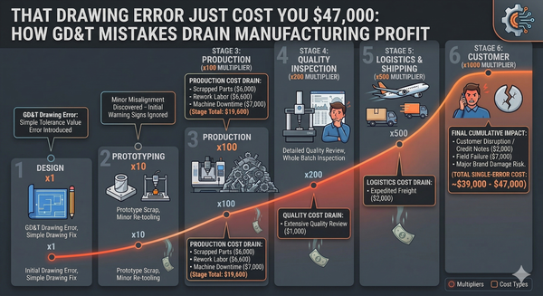
The cost to fix a design issue escalates dramatically the further downstream you catch it:
| Stage Where Defect Is Found | Relative Cost to Fix |
|---|---|
| Design Engineering | $1 (baseline) |
| Manufacturing Engineering | $2 |
| Production | $4 |
| Customer / Field | $5–$10+ |
The message is clear: fix it in the design, or pay for it forever in production.
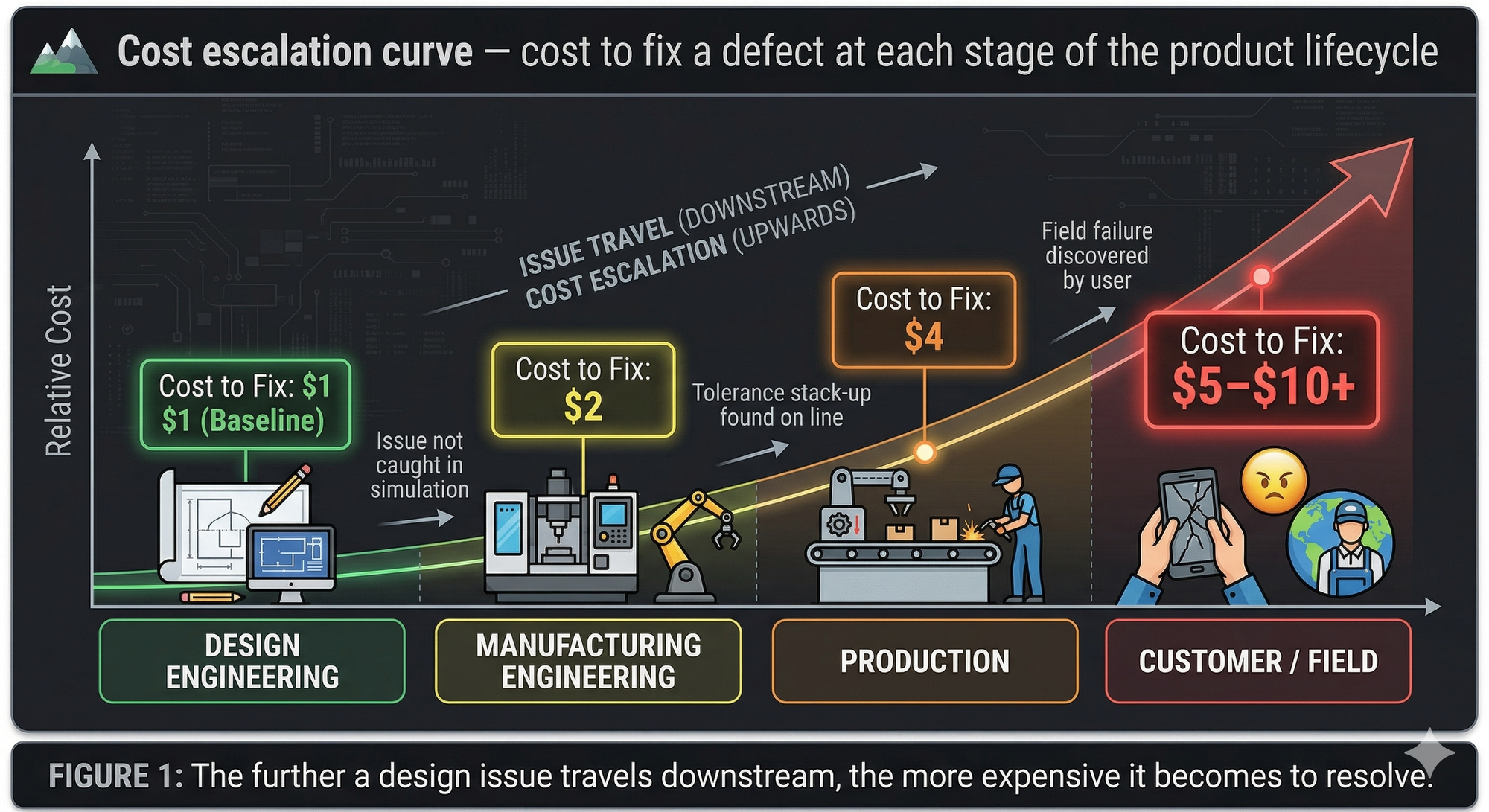
Figure 1: The further a design issue travels downstream, the more expensive it becomes to resolve.
Cost / Impact Analysis: Where the $20k Disappears
Let me walk you through a realistic scenario. Take a small manufacturer making 5,000 units per year of a fabricated steel assembly — a bracket, enclosure, or frame. Nothing exotic. Just bread-and-butter sheet metal and machined components.
Here's where design-driven waste typically hides:
| Design Issue | Annual Waste (Est.) | How It Shows Up |
|---|---|---|
| Over-tight tolerances on non-critical features | $4,000–$6,000 | Slower machining, higher scrap, more inspection |
| Excessive part count (extra fasteners, brackets) | $3,000–$5,000 | More purchasing, kitting, assembly time |
| Non-standard material or section sizes | $2,500–$4,000 | Premium pricing, longer lead times, excess offcuts |
| No consideration of standard tooling radii | $2,000–$3,000 | Custom tooling, extra setups, slower bending |
| Missing or unclear GD&T / drawing notes | $2,000–$3,500 | Misinterpretation, rework, quality disputes |
| Total Estimated Annual Waste | $13,500–$21,500 |
These aren't dramatic failures. They're quiet, persistent drains — the kind of costs that get absorbed into "normal" overhead and never questioned.
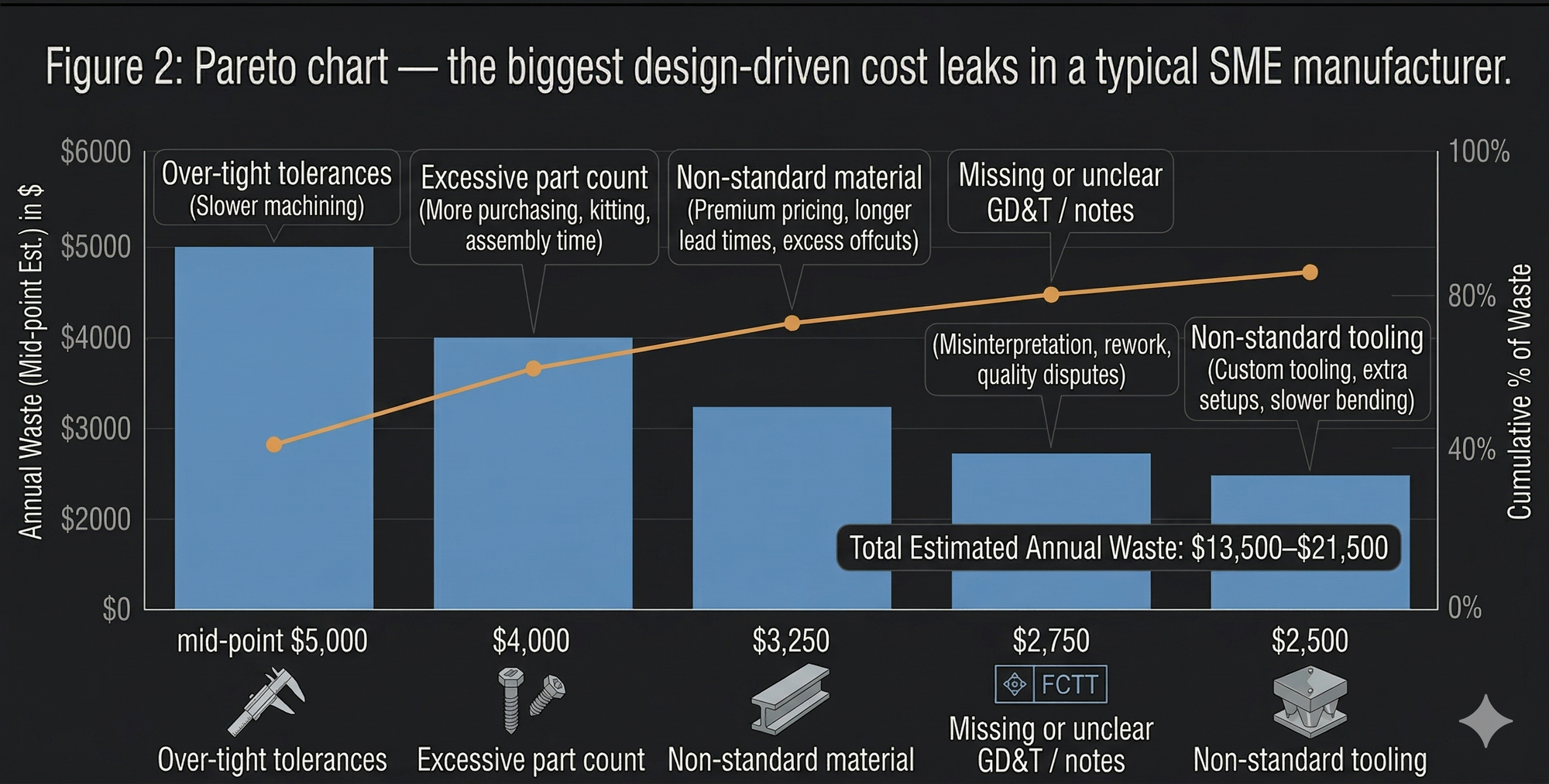
Figure 2: Pareto chart — the biggest design-driven cost leaks in a typical SME manufacturer.
The Solution: Five Design Changes That Pay for Themselves
Here are five practical, proven design changes I recommend to manufacturing clients. None of them require new equipment. All of them reduce cost.
1. Relax Tolerances on Non-Critical Features
This is the single biggest quick win in almost every workshop I walk into. Engineers (myself included, early in my career) default to tight tolerances because it feels safer. But tighter tolerances mean slower feeds, more passes, more inspection, and higher scrap.
The rule of thumb: If a feature doesn't mate with another part, seal against a surface, or bear a load — it probably doesn't need ±0.05 mm. General machining tolerances of ±0.25 mm or even ±0.5 mm are perfectly adequate for most non-functional dimensions.
| Tolerance Band | Typical Process Required | Relative Cost |
|---|---|---|
| ±0.5 mm | Standard milling/turning | 1× (baseline) |
| ±0.25 mm | Careful setup, moderate feeds | 1.5× |
| ±0.1 mm | Slow feeds, skilled operator | 2–3× |
| ±0.05 mm | Grinding or fine finishing | 5–10× |
Action step: Pull out your top 10 drawings by production volume. Highlight every tolerance. Ask: "Does this feature actually need to be this precise?" If you relax even 30% of tolerances on your highest-volume parts, you'll see immediate cycle time and scrap reductions.
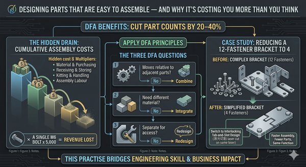
2. Reduce Part Count Through Design Simplification
Every additional part in your assembly costs money — not just in material, but in purchasing, receiving, storing, kitting, handling, and assembly labour. A single extra M6 bolt might seem trivial, but multiply it across 5,000 assemblies and you're looking at real labour and inventory cost.
Design for Assembly (DFA) principles can cut part counts by 20–40% in many products. Ask three questions about every part:
- Does it move relative to adjacent parts? If no, it might be combined.
- Does it need to be a different material? If no, it might be integrated.
- Does it need to be separate for assembly access? If no, redesign the geometry.
I've seen bracket assemblies with 12 fasteners reduced to 4 by switching to interlocking tab-and-slot designs cut on the same laser. Same function, fewer parts, faster assembly.
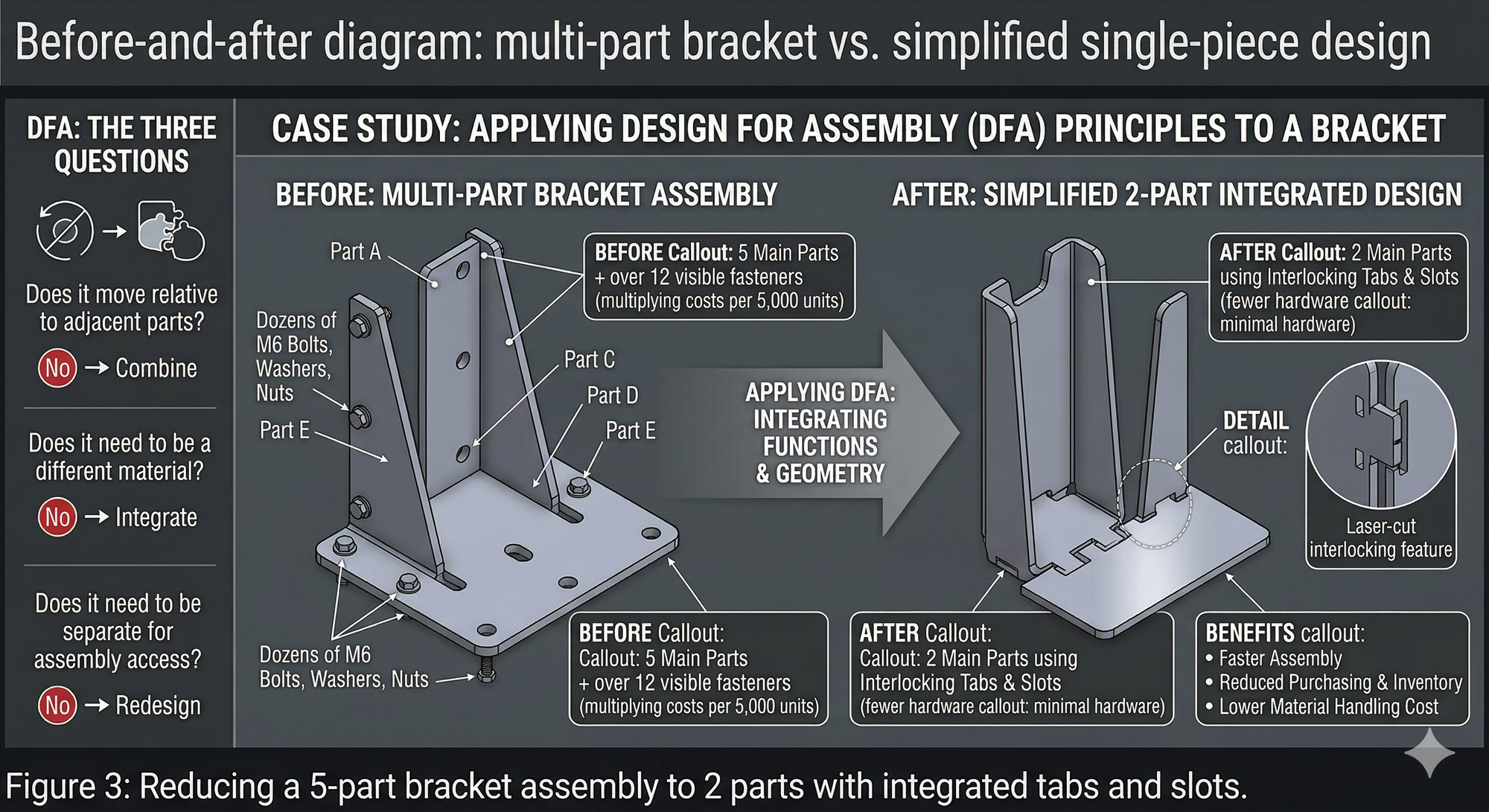
Figure 3: Reducing a 5-part bracket assembly to 2 parts with integrated tabs and slots.
3. Standardise Materials and Section Sizes
Using non-standard material grades or unusual section sizes is one of the most expensive habits in Australian manufacturing. Every non-standard item means minimum order quantities, longer lead times, and wasted offcuts.
Practical tips:
- Design around commonly available flat bar, angle, and RHS sizes stocked by local steel merchants. In Australia, that means working with AS/NZS standard sections wherever possible.
- Avoid specifying exotic grades (e.g., 316 stainless) when a cheaper alternative (e.g., 304, or even galvanised mild steel with coating) will do the job.
- Use standard sheet thicknesses: 1.6 mm, 2.0 mm, 3.0 mm, etc. Odd sizes like 2.5 mm or 4.5 mm often carry premium pricing and lead times.
The savings: Standardising materials across your product range often reduces raw material costs by 10–15% and slashes inventory holding.
4. Design to Standard Tooling and Processes
Every manufacturer has a set of existing tooling — press brake dies, drill sizes, punch tools, standard bending radii. When a designer ignores what's already on the shop floor, they force new setups, custom tooling, or outsourcing — all of which cost money.
Common offenders:
- Specifying a bend radius that doesn't match any existing press brake die.
- Calling out a hole size that requires a special drill or reamer rather than a standard metric drill.
- Designing features that can't be accessed with existing CNC tooling without a custom fixture.
Action step: Create a "shop capability sheet" — a one-page summary of your standard tooling, bend radii, hole sizes, and machine envelopes. Give it to every designer. Make it a checkpoint before any drawing goes to production.
| Design Element | Preferred Standard (Example) |
|---|---|
| Bend radii (sheet metal) | Match existing press brake tooling (e.g., 2 mm, 3 mm, 5 mm internal radius) |
| Hole sizes | Standard metric drill sizes (e.g., 5.0, 6.0, 8.0, 10.0 mm) |
| Thread sizes | M5, M6, M8, M10 — avoid BSW, UNC unless customer-specified |
| Sheet thickness | 1.6, 2.0, 3.0, 4.0, 5.0, 6.0 mm (locally stocked gauges) |
5. Fix Your Drawing Notes and GD&T
Ambiguous drawings cause arguments, rework, and wasted time. I've seen shop floor operators spend 20 minutes debating what a drawing means — on a part that takes 10 minutes to make. Multiply that across a week and the cost is staggering.
The most common drawing problems I see:
- Missing general tolerance notes (so the machinist guesses).
- No surface finish callouts (so every surface gets treated the same).
- Inconsistent or missing GD&T symbols (so flatness, perpendicularity, and position are left to interpretation).
- Outdated revision blocks (so the wrong version gets made).
The fix: Establish a standard drawing template with a general tolerance block, surface finish defaults, and a clear revision control process. Every drawing that leaves design should answer one question without ambiguity: "Can the operator make this part correctly, first time, without asking anyone?"
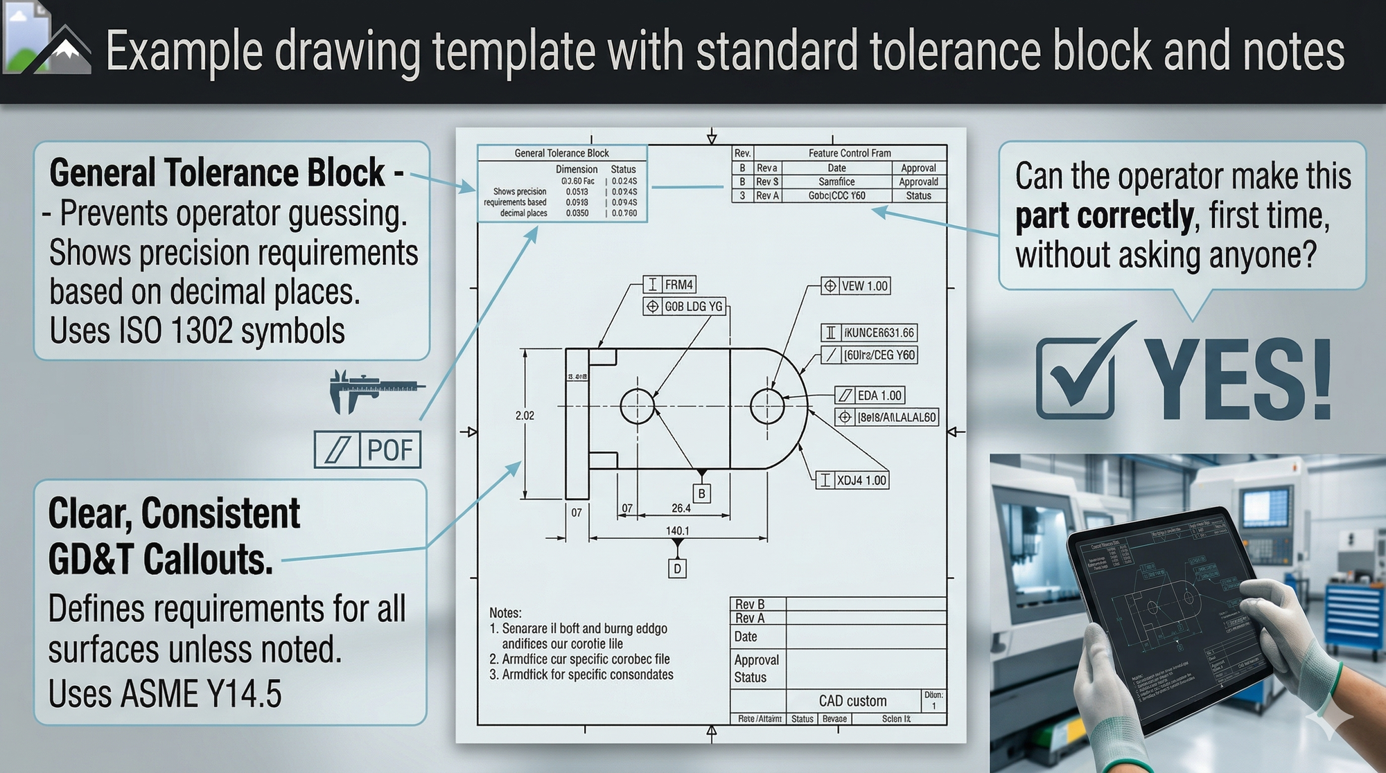
Figure 4: A well-structured drawing template eliminates interpretation errors on the shop floor.
Bringing It All Together: The Design Cost Review
These five changes work best when you systematise them. I recommend a quarterly Design Cost Review — a structured 2-hour session where engineering and production sit down together and review the top 20 parts by volume or cost.
Design Cost Review Checklist:
- [ ] Are all tolerances justified and matched to process capability?
- [ ] Can any parts be combined or eliminated?
- [ ] Are all materials standard, locally available stock?
- [ ] Does the design use existing tooling and standard processes?
- [ ] Are drawings clear, complete, and unambiguous?
- [ ] Has production flagged any recurring issues with these parts?
This single practice — reviewing designs through the lens of cost — is where engineering skill meets business impact. It's where a toolmaker's eye and a strategist's mindset come together.

Figure 5: A quarterly Design Cost Review bridges the gap between engineering and production.
Takeaway
Your product design is the biggest determinant of your manufacturing cost — and the most overlooked one. You don't need new machines or a bigger team to save $20k a year. You need smarter drawings, standardised processes, and a deliberate habit of reviewing designs for cost, not just function. The manufacturers who build this discipline into their engineering process consistently outperform those who don't.
Design for function. Then redesign for profit.
Ready to Find Your Hidden Design Savings?
If you suspect your drawings are costing more than they should — or you've never done a structured Design Cost Review — I can help. I offer a short CostDown Audit to walk through your highest-volume parts and identify where simple design changes will deliver the fastest payback.