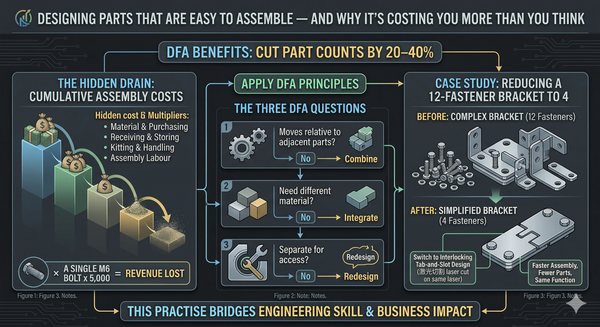
That Drawing Error Just Cost You $47,000 - How GD&T Mistakes Drain Manufacturing Profit
A single tolerance mistake in a drawing can quietly trigger rework, scrap, and delays—costing tens of thousands. For SMEs on tight margins, GD&T errors are a major hidden cost. Here’s how they happen, what they cost, and how to fix them.

The Problem: Tolerances That Don't Match Reality
Here's a scenario I've seen play out more than once on the shop floor.
A designer specifies a positional tolerance of ±0.05 mm on a bolt hole pattern. It looks fine on screen. The drawing gets released. The CNC operator programs the part, runs a batch of 200 units, and sends them to assembly. Half the batch doesn't fit the mating part. The holes are technically within the stated tolerance — but the datum references were wrong, the material condition modifier was missing, and the feature control frame didn't reflect the actual assembly requirements.
Nobody lied. Nobody was lazy. The drawing just didn't communicate the design intent clearly enough for the people who had to make and inspect the part.
This is the core issue with GD&T errors. They don't look like mistakes on paper. They look like properly dimensioned drawings. The failure only surfaces downstream — at the CNC machine, in the assembly cell, at the customer's incoming inspection, or worse, in the field.
After 25 years in manufacturing — from the toolmaking bench to R&D design engineering to full production line commissioning — I can tell you this: the drawing is the most expensive document in your factory. When it's wrong, everything that follows is wrong. And every step downstream multiplies the cost.
Where GD&T Errors Actually Happen
GD&T errors aren't exotic. They follow predictable patterns, and most fall into a handful of categories that I've seen repeated across sheet metal, machined components, welded assemblies, and even architectural hardware.
1. Over-Tolerancing (The "Play It Safe" Trap)
Designers apply tight tolerances everywhere, thinking it guarantees quality. In reality, it guarantees high production cost, slow cycle times, excessive inspection, and inflated reject rates — even for parts that would function perfectly at a looser tolerance. Unnecessary GD&T application can increase manufacturing costs by 50% or more on individual components.
Example: A laser system can cut at 140 inches per minute. A machining centre achieving unnecessarily tight GD&T tolerances operates at 20 inches per minute. You pay more for labour, more for material removal, and more for scrap — then spend additional time on setup, operations planning, and back-end inspection.
2. Wrong or Missing Datum References
Datums define the reference framework for every geometric tolerance on the drawing. If the datum scheme doesn't match how the part is fixtured, machined, or assembled, the tolerance is meaningless. The part might measure "in spec" on paper but fail in the real world.
3. Incorrect Material Condition Modifiers (MMC, LMC, RFS)
Material condition modifiers define how size and geometric tolerances interact. Misusing Maximum Material Condition (MMC), Least Material Condition (LMC), or Regardless of Feature Size (RFS) introduces ambiguity in how parts are measured and assembled. The result: rework on parts that shouldn't need it, or nonconforming parts slipping through.
4. Incomplete Feature Control Frames
Missing symbols, incorrect syntax, or incomplete feature control frames lead to misinterpretation during manufacturing and inspection. If the machinist and the quality inspector read the same drawing differently, you're going to have problems — and neither of them is wrong. The drawing is.
5. Ignoring Assembly Context
Tolerancing a part in isolation — without considering how it mates, fastens, seals, or loads against adjacent components — is a common and costly error. GD&T that doesn't reflect real assembly conditions causes misalignment, reduced performance, and assembly rework.
6. Relying on Title Block Tolerances for Critical Features
General title block tolerances apply broad limits that may be completely insufficient for features that affect fit, function, or durability. Critical features need specific callouts.
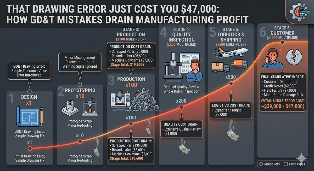
The Cost: What GD&T Errors Actually Drain From Your Business
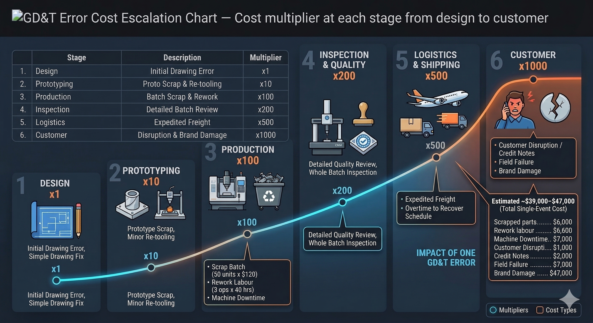
The financial impact of GD&T errors follows a well-established escalation model. The relative cost to correct a defect increases dramatically the further downstream it's detected:
| Stage Where Defect Is Detected | Relative Cost to Fix |
|---|---|
| Design Engineering | $1 (baseline) |
| Manufacturing Engineering | $2 |
| Production / Shop Floor | $4 |
| Customer / Field | $5 – $10+ |
For a mid-sized Australian manufacturer turning over $5–10 million per year, scrap and rework typically costs around 2.2% of annual revenue. On $8M revenue, that's $176,000 per year disappearing into rework bays, scrap bins, and overtime.
Now consider that GD&T-related issues are frequently a major contributor to that rework figure. Here's a realistic cost breakdown for a single GD&T error event in a typical SME:
| Cost Element | Estimated Cost |
|---|---|
| Scrapped parts (50 units × $120 material) | $6,000 |
| Rework labour (3 operators × 40 hrs × $55/hr) | $6,600 |
| Machine downtime (re-setup, re-run) | $4,800 |
| Inspection & quality review | $2,400 |
| Expedited freight (replacement order) | $3,200 |
| Customer disruption / credit note | $8,000 |
| Engineering investigation & drawing revision | $2,500 |
| Overtime to recover schedule | $5,500 |
| Total single-event cost | ~$39,000–$47,000 |
And that's one event. In shops without robust drawing review processes, these events repeat quarterly — or monthly.
The Hidden Multiplier: Rolled Throughput Yield
Here's where it gets worse. If you have 50 process steps and each delivers 99% first-pass yield, your rolled throughput yield (RTY) — the percentage of units that make it through every step without any rework — is only about 60%. One percent loss per step sounds minor. Across a full production process, it's a disaster.
GD&T errors don't just create one failure point. They create cascading failures across multiple downstream operations: machining, bending, welding, assembly, inspection. Every station that touches a part made from a bad drawing is a station that wastes time, material, and capacity.
The Fix: A Practical GD&T Quality System for SMEs
You don't need a PhD in metrology to fix this. You need discipline, a few simple processes, and a commitment to treating the engineering drawing as a controlled, business-critical document.
Step 1: Implement a Drawing Review Gate Before Release
No drawing should reach the shop floor without a structured review. This doesn't need to be a formal PPAP-level process (though if you're supplying automotive or aerospace, it should be). At minimum, every drawing should pass through a checklist:
- Are datum references consistent with fixturing and assembly?
- Are material condition modifiers (MMC/LMC/RFS) applied correctly?
- Are feature control frames complete and syntactically correct?
- Do tolerances reflect functional requirements, not "safe" defaults?
- Has a tolerance stack-up been reviewed for critical assemblies?
- Has the drawing been reviewed by someone from manufacturing, not just design?
Cost to implement: A few hours of engineering time per drawing release. Cost of skipping it: $39,000+ per error event.
Step 2: Cross-Functional Drawing Reviews
The single most effective prevention measure is getting a machinist, a toolmaker, or a production engineer to review the drawing before release. Designers see intent. Manufacturers see reality. The gap between those two perspectives is where rework lives.
In my experience commissioning production lines and designing jigs and fixtures, the best results come when the person who will fixture and machine the part reviews the GD&T before it's finalised. This is not a luxury. It's a cost-reduction strategy.
Step 3: Standardise Your Drawing Practices
Adopt a consistent GD&T standard across your business — either ASME Y14.5 (common in North America and parts of Asia-Pacific) or ISO 1101 (common in Europe and increasingly in Australia). Don't mix them. Train your team on one standard and enforce it.
Key differences to be aware of:
| Aspect | ASME Y14.5 | ISO 1101 / GPS |
|---|---|---|
| Default rule | Envelope Principle (size and form linked) | Independency Principle (each tolerance independent) |
| Structure | Unified, practical | Modular, mathematically rigorous |
| Common use | North America, Asia-Pacific | Europe, global supply chains |
Step 4: Track Rework by Root Cause
You can't fix what you don't measure. Start tracking rework with a simple root-cause tag. When parts come back for rework, categorise the cause:
- Drawing error (GD&T, dimension, missing note)
- Material defect
- Machine/process variation
- Operator error
- Tooling wear
Within 90 days, you'll have data showing exactly where your money is going. In most shops I've worked in, drawing-related errors are in the top three causes — and they're the most preventable.
Rework Rate Formula:
Rework Rate (%) = (Rework Hours ÷ Productive Labour Hours) × 100
If your gross profit margin is 40% and you're losing 2–3% to rework, that's a significant chunk of your bottom line. Even a 1% reduction in rework rate on $8M revenue recovers $80,000 per year.
Step 5: Invest in GD&T Training — Starting With Designers
This is the highest-ROI training investment you can make. A two-day GD&T course for your design team costs $2,000–$4,000 per person. A single rework event from a GD&T error costs ten times that.
Training should cover:
- Correct application of feature control frames
- Datum selection aligned to manufacturing and assembly
- Proper use of material condition modifiers
- Tolerance stack-up analysis for assemblies
- Reading and interpreting GD&T on the shop floor (for machinists and inspectors)
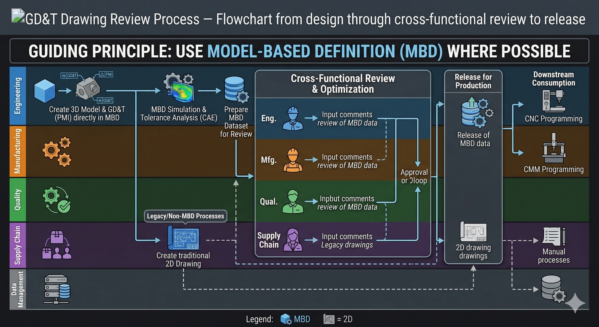
Step 6: Use Model-Based Definition (MBD) Where Possible
If you're using SolidWorks, Creo, or Inventor, embed GD&T directly into your 3D models. This creates a single source of truth, reduces manual transcription errors between 3D models and 2D drawings, and enables automated CMM inspection programming.
MBD doesn't replace the need for good GD&T knowledge — it amplifies it. A wrong tolerance embedded in a 3D model propagates errors just as efficiently as a wrong tolerance on a 2D drawing.
The Strategic View: Drawing Quality Is a Cash Flow Lever
Most manufacturers think of GD&T as a technical issue. It's not. It's a financial issue.
Every drawing that reaches the shop floor with an error is a cash flow leak. It consumes labour hours that should be productive. It scraps material that's already been paid for. It delays shipments that should be generating revenue. And it erodes customer confidence, which is the hardest cost to recover.
I've spent my career helping manufacturing businesses find and fix exactly these kinds of hidden cost drivers — from fixture redesign and standardised work to full production line commissioning. GD&T quality is one of the fastest-payback improvements available to any SME, because it prevents problems rather than just fixing them.
The cost of getting it right at the drawing stage is a rounding error compared to the cost of getting it wrong on the shop floor.
Key Takeaway
The engineering drawing is the most expensive document in your factory. A disciplined GD&T review process — backed by cross-functional input, standardised practices, and root-cause rework tracking — is one of the fastest, lowest-cost ways to reduce scrap, cut rework, and protect your margins. Fix the drawing, and you fix the production line.
Ready to Find the Cost Leaks in Your Operation?
If GD&T errors, rework, and scrap are eating into your margins, you're not alone — but you don't have to accept it. I offer a short CostDown Audit to help manufacturing businesses identify hidden cost drivers and build a practical plan to eliminate them. No fluff. No theory. Just engineering-led, financially focused solutions that pay for themselves.